Why 5G Stands Far Away from 4G

1. Introduction: two different design philosophies
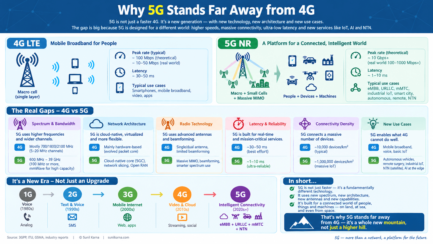
4G (LTE/LTE-Advanced) was designed around one dominant use case: mobile broadband for smartphones. Its air interface was fixed early (15 kHz subcarrier spacing, 1 ms subframe, always-on reference signals, a monolithic packet core) and every later release had to stay backward compatible with it. 5G (NR, New Radio) was designed from day one around three use-case families defined by ITU-R (IMT-2020), and every design decision (numerology, frame structure, MIMO, core network) was made to serve all three at once.
KPI | 4G (IMT-Advanced / typical LTE-A) | 5G (IMT-2020 target) |
|---|---|---|
Peak data rate (DL) | ~1 Gbps target (practically 0.4–2 Gbps with carrier aggregation) | 20 Gbps |
Peak data rate (UL) | ~0.5 Gbps target | 10 Gbps |
User-experienced rate | ~10 Mbps | 100 Mbps (up to 1 Gbps in hotspots) |
Peak spectral efficiency (DL) | 15 bps/Hz | 30 bps/Hz |
User-plane latency | ~10 ms target (20–40 ms RTT in real networks) | 1 ms (URLLC), 4 ms (eMBB) |
Connection density | ~100,000 devices/km² (with NB-IoT/LTE-M overlays) | 1,000,000 devices/km² |
Area traffic capacity | ~0.1 Mbps/m² | 10 Mbps/m² |
Mobility | up to 350 km/h | up to 500 km/h |
Network energy efficiency | 1× (baseline) | 100× improvement target |
The three headline use cases are:
- eMBB (enhanced Mobile Broadband): ultra-high throughput
- mMTC (massive Machine-Type Communication): ultra-large number of connections
- URLLC (Ultra-Reliable Low-Latency Communication): ultra-low latency and very high reliability
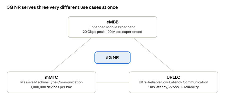
use-case triangle · KPIs from the IMT-2020 table above
Every NR design choice had to serve all three corners at once; LTE was tuned for the top corner only.
Let us take each one apart.
2. eMBB: why 5G delivers ultra-high throughput
2.1 The physics: Shannon capacity
Every throughput gain in wireless traces back to the Shannon–Hartley relationship, extended with spatial multiplexing:
C ≈ N_layers × B × log2(1 + SINR)
There are only three levers: more bandwidth (B), better SINR / higher modulation (spectral efficiency) and more spatial layers (N_layers). 5G pulls all three much harder than LTE could.
2.2 Lever 1: Bandwidth (spectrum)
Parameter | LTE | 5G NR |
|---|---|---|
Max bandwidth per carrier | 20 MHz | 100 MHz (FR1, sub-7.125 GHz), 400 MHz (FR2, mmWave) |
Carrier aggregation | up to 5 CCs in Rel-10 (32 in spec, rarely deployed beyond 3–5) | up to 16 CCs |
Max aggregated bandwidth (spec) | 100 MHz (practical) | 6.4 GHz (spec), 800 MHz–1.6 GHz commonly deployed in mmWave |
Frequency range | 700 MHz – 2.6 GHz (mostly below 3 GHz) | FR1: 410 MHz–7.125 GHz; FR2: 24.25–52.6 GHz (extended to 71 GHz in Rel-17) |
Why 4G cannot do this: LTE's physical layer is built around a fixed 15 kHz subcarrier spacing and a maximum FFT size of 2048, which caps a single carrier at 20 MHz. Going to 100–400 MHz carriers would require either a much larger FFT (more complexity) or a wider subcarrier spacing, which LTE does not support. Furthermore, LTE was never specified for frequencies above ~6 GHz; its timing advance, CP length and reference signal design assume cell radii of kilometers and low-frequency propagation. Carrier aggregation is the workaround, but each component carrier carries its own overhead and signaling, so it scales poorly.
2.3 Flexible numerology: the key enabler
5G NR introduces scalable subcarrier spacing:
SCS = 15 × 2^μ kHz where μ = 0, 1, 2, 3, 4
μ | SCS | Slot duration | Typical use |
|---|---|---|---|
0 | 15 kHz | 1 ms | Low bands (<1 GHz), wide coverage, IoT |
1 | 30 kHz | 0.5 ms | Mid-band (3.5 GHz) eMBB |
2 | 60 kHz | 0.25 ms | Mid-band / mmWave |
3 | 120 kHz | 0.125 ms | mmWave (FR2) |
4 | 240 kHz | 62.5 µs | SSB in FR2 |
Wider subcarrier spacing means shorter symbols, which gives (a) more tolerance to phase noise and Doppler at high frequencies, and (b) allows large bandwidths with a manageable FFT size. LTE has exactly one numerology (15 kHz), so it cannot adapt.
Bandwidth efficiency also improves. In LTE, a 20 MHz channel carries 100 PRBs, i.e., 18 MHz of usable subcarriers (90 % occupancy). In NR, a 100 MHz channel at 30 kHz SCS carries 273 PRBs × 12 × 30 kHz = 98.3 MHz (98 % occupancy), so guard-band waste drops from 10 % to about 2 %. (Each PRB contains 12 consecutive subcarriers in the frequency domain)
2.4 Lever 2: Spectral efficiency
Higher-order modulation. LTE supports 64QAM (UL) and 256QAM (DL, from Rel-12, optional). NR supports 256QAM in both directions and 1024QAM in later releases for specific scenarios.
Better channel coding. This is a major, often overlooked difference.
LTE | 5G NR | |
|---|---|---|
Data channel | Turbo code (serial decoding structure) | LDPC (highly parallel decoding) |
Control channel | Tail-biting convolutional code | Polar code |
LDPC decoders parallelize naturally, so they sustain multi-Gbps rates with low decoding latency and perform better at high code rates and large block sizes. Turbo decoders are inherently iterative and sequential, which becomes a hardware bottleneck at Gbps rates.
Lean carrier design. LTE transmits Cell-specific Reference Signals (CRS) in every subframe on every antenna port, whether or not any user is being served. This costs roughly 5–15 % of resources depending on antenna count and is the single biggest source of overhead. NR removed always-on CRS: demodulation uses UE-specific DMRS (sent only when data is sent), channel sounding uses on-demand CSI-RS, and the only always-on signal is the SSB (default period 20 ms). Result: higher payload per resource and lower interference.
2.5 Lever 3: Massive MIMO and beamforming
LTE | 5G NR | |
|---|---|---|
Max DL layers per UE | 8 (practically 2–4) | 8 (practically 4) |
MU-MIMO layers per cell | up to 4 (limited by codebook feedback) | up to 12+ with massive MIMO |
Base-station antenna elements | 2–8 ports, passive antennas | 32–256 active elements (64T64R typical) |
Beamforming | Mostly cell-wide with some TM7–TM9 | Native, with beam management (up to 64 SSB beams in FR2) |
Why massive MIMO works in 5G and not in 4G.
1. Beamforming gain: an array of N antennas gives array gain of roughly 10·log10(N) dB (≈18 dB for 64 elements), which compensates for the extra path loss at higher frequencies (free-space path loss grows with f²; moving from 2 GHz to 28 GHz costs about 23 dB).
2. TDD channel reciprocity: most 5G mid-band is TDD, so the gNB measures the uplink SRS (Sounding Reference Signal) and derives the downlink channel directly. LTE was primarily FDD, where the UE must feed back the channel (codebook-based CSI), and feedback overhead grows linearly with antenna count, making large arrays impractical.
3. MU-MIMO: with accurate CSI, the gNB serves many UEs on the same time-frequency resource with spatially separated beams, multiplying cell capacity.
4. Short wavelength: at 3.5 GHz and above, 64+ elements fit inside a radio unit of reasonable size. At 700–1800 MHz, the same array would be impractically large.
2.6 Putting numbers on it: the 3GPP peak-rate formula
The formula from 3GPP TS 38.306 calculates the theoretical maximum data rate of a 5G NR radio connection under specified radio conditions. It estimates how many information bits can be transmitted per second based on the number of spatial layers, modulation order, coding rate, available resource blocks, subcarrier spacing, and radio-resource overhead.

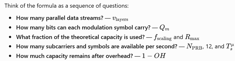
Example A: NR FR1, 100 MHz, 30 kHz SCS, 4 layers, 256QAM
- N_PRB = 273, T_s = 35.7 µs → 273 × 12 / 35.7 µs = 91.7 M resource elements/s per layer
- Rate ≈ 4 × 8 × 0.926 × 91.7 M × 0.86 ≈ 2.34 Gbps
Example B: NR FR2, 400 MHz, 120 kHz SCS, 2 layers, 256QAM
- N_PRB = 264, T_s = 8.93 µs → 354.8 M RE/s per layer
- Rate ≈ 2 × 8 × 0.926 × 354.8 M × 0.82 ≈ 4.3 Gbps per carrier, so four aggregated carriers give about 17 Gbps
LTE comparison: one 20 MHz LTE carrier with 4×4 MIMO and 256QAM gives about 400 Mbps. Reaching 2 Gbps requires aggregating five carriers (100 MHz), each with its own CRS overhead and control signaling, which is very hard in real spectrum holdings.
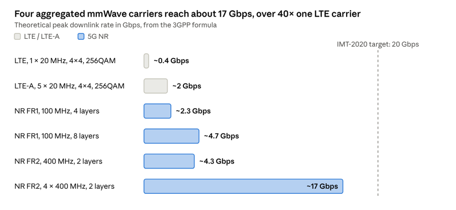
3GPP TS 38.306 peak-rate formula · theoretical, approximate
These are lab-ideal peaks; real users see far less, but the ratio between LTE and NR carriers holds.
2.7 The cost of eMBB: mmWave reality
The extra spectrum comes with physics penalties. Free-space path loss at 28 GHz is about 23 dB higher than at 2 GHz, building penetration loss is 20–40 dB, and human-body blockage adds another 20+ dB. This is why 5G requires dense small cells, beam tracking and fast beam-recovery procedures, none of which exist in LTE.
3. mMTC: why 5G supports ultra-large connection density
3.1 The target
ITU-R M.2412 defines the mMTC requirement as 1,000,000 devices per km², with devices sending small packets (e.g. 32 bytes) infrequently (e.g. every 2 hours) and 99 % of packets delivered within 10 seconds.
A quick feasibility check shows why this is hard. With an inter-site distance of 500 m, one site covers about 0.22 km², and there are about 4.6 sites per km². One million devices per km² therefore means roughly 200,000 devices per site, of which only a tiny fraction transmit at any given moment. The challenge is not throughput; it is signaling, context and control-channel scalability.
3.2 Why classic 4G (LTE for smartphones) struggles
1. Connection setup is signaling-heavy. Moving a device from RRC_IDLE to RRC_CONNECTED takes a random-access procedure plus roughly ten or more RRC and NAS messages, and the MME/S-GW must create per-device bearer contexts. For a 32-byte sensor reading, the signaling can be larger than the payload.
2. Per-cell RRC-connected user limits. Base-station hardware and software support only hundreds to a few thousand connected contexts per cell.
3. Control channel capacity. The PDCCH occupies the first 1–3 OFDM symbols of each subframe and can schedule only a limited number of users per millisecond.
4. Minimum resource granularity. The smallest schedulable unit is a 180 kHz PRB pair. Allocating that to a few bytes is spectrally wasteful.
5. Random-access storms. With only 64 preambles per PRACH occasion (about 54 for contention-based access), simultaneous attempts from many devices lead to heavy collisions.
6. Power and cost. Cat-4 LTE modems are complex and power-hungry, which kills multi-year battery life.
An honest note: 3GPP Release 13 added NB-IoT (180 kHz carrier) and LTE-M (Cat-M1) as IoT extensions to LTE. These are bolt-on solutions, and 3GPP has designated both as part of the 5G mMTC family. What plain LTE for smartphones lacks, and what 5G adds natively, is a system-wide design for massive connectivity.
3.3 How 5G achieves massive connectivity
Mechanism | What it does | Why it matters |
|---|---|---|
RRC_INACTIVE state | The device keeps its RAN and core context while idle; resume takes far fewer messages than a full setup | Cuts signaling and latency for intermittent traffic |
Small Data Transmission (Rel-17) | Sends data during random access or with a configured grant without a full RRC resume | Removes connection-setup overhead for tiny payloads |
2-step RACH (Rel-16) | Merges preamble and message into one round trip | Lower latency and fewer collisions |
Massive MIMO + MU-MIMO | Many devices share the same time-frequency resource on different beams | Spatial reuse multiplies connection capacity |
Flexible numerology and BWP | Narrow-band operation and bandwidth parts tuned to device class | Efficient resource use for small payloads |
RedCap (Rel-17) | Reduced-capability devices: 20 MHz in FR1, 1–2 antennas, up to ~150 Mbps | Cheap, low-power wearables, cameras and industrial sensors |
Power saving (eDRX, PSM, wake-up signals) | Devices sleep for minutes to days | 10+ year battery life |
Cloud-native core with slicing | A dedicated slice isolates massive IoT traffic from broadband | Predictable capacity and QoS |
NB-IoT/LTE-M on 5G core | Coverage extension through repetitions (up to 2048), maximum coupling loss ~164 dB, plus data over the control plane | Deep-indoor and underground reach |
The core is just as important as the radio. The 4G EPC uses a small number of large, monolithic nodes (MME, S-GW, P-GW) that scale vertically. The 5G core is a service-based architecture (SBA) of microservice network functions (AMF, SMF, UPF, UDM and others) that scale horizontally and independently, so signaling load from millions of devices can be absorbed by simply adding AMF instances.
4. URLLC: why 5G delivers ultra-low latency
4.1 The target
IMT-2020 requires 1 ms user-plane latency for URLLC and 99.999 % reliability (packet error rate 10⁻⁵ for a 32-byte packet within 1 ms). Control-plane latency target is 20 ms (4G: 50 ms). Typical applications: industrial automation, remote surgery, autonomous driving, smart grid protection.
4.2 Where LTE's latency comes from
Let's trace an LTE uplink packet from a device in RRC_CONNECTED state:
Step | Typical LTE delay |
|---|---|
Wait for next Scheduling Request (SR) opportunity | 0.5–5 ms (avg. ~2.5 ms) |
SR transmission | 1 ms |
eNB processing and UL grant | 3 ms |
UE processing before transmitting (k=4 rule) | 4 ms |
Data transmission (1 ms TTI) | 1 ms |
eNB decoding | ~3 ms |
Total UL air-interface latency | ~12–15 ms |
HARQ retransmission (each) | +8 ms (fixed 8 ms HARQ RTT in FDD) |
Add core network traversal (eNB → S-GW → P-GW at a centralized site, often 10–30 ms) and you reach the 20–40 ms that real 4G networks show. The architecture simply has no path to 1 ms.
4.3 How 5G NR cuts latency
1. Shorter transmission time
- Slot length scales with numerology: 1 ms (15 kHz) down to 0.125 ms (120 kHz)
- Mini-slots of 2, 4 or 7 OFDM symbols can start at any symbol position, not just at slot boundaries. At 120 kHz, a 2-symbol mini-slot lasts about 18 µs
2. Self-contained slot structure (especially TDD)
A single slot can contain DL control, DL data, guard period and UL ACK/NACK, so feedback arrives within the same slot rather than 4 ms later.
3. Faster HARQ and relaxed processing times
LTE fixes UE processing at 4 ms (n+4 timing). NR defines UE processing capability levels where PDSCH-to-ACK delay is just a fraction of a slot to a few symbols, and the K1 timing is signaled dynamically.
4. Grant-free (configured grant) uplink
Instead of SR → grant → data, the UE gets pre-allocated periodic resources (Type 1 and Type 2 configured grants) and transmits immediately, saving ~5–8 ms.
5. Pre-emption and prioritization
A URLLC packet can puncture an ongoing eMBB transmission (DL pre-emption indication) and use logical-channel prioritization on UL, so it never waits for a long eMBB transmission to finish.
6. Reliability toolbox
- Low-rate CQI/MCS tables targeting BLER 10⁻⁵
- Slot aggregation and repetitions
- PDCP duplication over two carriers/paths
- Multi-TRP transmission for spatial diversity
- Robust PDCCH with high aggregation levels
7. Core and transport flattening
- Control/User-plane separation (CUPS): the UPF is decoupled from the control plane and can be placed close to the gNB
- Multi-access Edge Computing (MEC) hosts applications at the edge, removing tens of ms of backhaul and internet round trip
- Rel-16 adds Time-Sensitive Networking (TSN) integration for deterministic delivery in factories
Latency component | LTE | 5G NR |
|---|---|---|
Transmission time interval | 1 ms (fixed) | 0.125–1 ms, mini-slot down to ~18 µs |
HARQ round-trip | 8 ms (FDD) | ~1–2 slots (sub-ms at high numerology) |
UL access | SR + grant (≥ 8 ms) | Configured grant (0 extra round trips) |
UE processing | 4 ms fixed | Flexible, 0.1–1 ms class |
Core path | Centralized EPC | Distributed UPF + MEC |
Typical user-plane latency | ~15–40 ms | ~1–10 ms (SA + edge); <1 ms air-interface (URLLC) |
Reality check: many early 5G deployments are NSA (non-standalone, anchored on the LTE core), which means they inherit 4G core latency. True URLLC needs 5G SA + edge UPF + URLLC-configured RAN.
5. Other powerful 5G features that 4G does not have
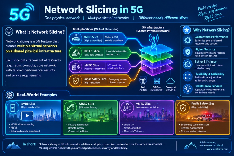
5.1 Network slicing
A slice is a logically isolated end-to-end network (RAN + transport + core) identified by an S-NSSAI (Slice/Service Type plus Slice Differentiator), with its own QoS, security and resource guarantees. One physical network can run an eMBB slice, an IoT slice and a mission-critical slice at the same time. LTE offers only dedicated bearers and a single APN-based QoS model (QCI), with no end-to-end isolation.
The diagram above outlines the End-to-End (E2E) 5G Network Slicing framework, demonstrating how a single physical infrastructure is partitioned into logically isolated virtual networks tailored to diverse vertical applications:
- Physical Infrastructure Layer (Bottom): Encompasses the physical Access Network (RAN/gNodeBs), Transport Network (fronthaul/backhaul routers), Edge/Core Data Centers, and Cloud functions (AMF, SMF, UPF).
- Logical Slice Layer (Top): Illustrates independent vertical slices—such as Smart Home/eMBB, Autonomous Driving/URLLC, and Factory Automation—each operating with customized SLA parameters (latency, bandwidth, reliability, and security).
- Orchestration & Management (Right): Managed by automated OSS/BSS, MANO, and AI/Big Data engines that dynamically provision, scale, and isolate network slices across domains.
5.2 Service-Based Architecture (cloud-native core)
Network functions talk to each other through HTTP/2 REST APIs on a service bus, run as containers, scale independently, and are upgraded without taking the network down. The EPC relies on point-to-point GTP/Diameter interfaces between fixed boxes.
5.3 Beam management
In FR2, the gNB sweeps SSB beams (up to 64), the UE reports the best beam, and the network refines it with CSI-RS and tracks it as the user moves, with beam-failure recovery. LTE has no concept of beam-level mobility.
5.4 Bandwidth Parts (BWP) and energy efficiency
A UE can operate on a small BWP when idle or sending light traffic and switch to a wide BWP for bulk transfers. Combined with lean carrier design, wake-up signaling, and SSB periodicity of 20 ms (instead of always-on CRS), the network can sleep far more of the time. This is essential for the 100× energy-efficiency goal.
5.5 Dynamic Spectrum Sharing (DSS)
NR and LTE can share the same carrier, with NR scheduled around LTE's CRS, allowing a smooth refarming of 4G spectrum.
5.6 Flexible duplexing and dynamic TDD
Symbols in a slot can be flexibly assigned to DL, UL or flexible, per slot or per cell. This helps with asymmetric traffic. Future releases explore sub-band full duplex.
5.7 Open and disaggregated RAN
4G | 5G | |
|---|---|---|
RAN split | BBU + RRH (CPRI, vendor proprietary) | CU / DU / RU with standardized F1 and eCPRI-based fronthaul (split 7.2x), O-RAN interfaces |
Virtualization | Rare | vRAN/Cloud RAN on COTS servers |
Intelligence | SON | RAN Intelligent Controller (xApps/rApps) |
5.8 Integrated Access and Backhaul (IAB)
Integrated Access and Backhaul (IAB) is a 5G technology that allows a base station to use the same 5G NR radio infrastructure for two purposes: connecting with user devices and providing wireless backhaul connectivity to other base stations.
In simple terms, IAB allows a 5G base station to connect to the core network through another 5G base station, instead of requiring its own dedicated fiber or microwave backhaul link.
This is especially useful where installing fiber is expensive, difficult, or time-consuming.
5.9 Positioning, V2X (Vehicle-to-Everything), unlicensed and non-terrestrial
5G NR is more than a faster mobile broadband technology. The 3GPP specifications extend it to support precise positioning, connected vehicles, additional spectrum through unlicensed bands, and connectivity through satellites and other non-terrestrial platforms. These capabilities were introduced and enhanced across different 3GPP releases.
- Positioning: Rel-16 multi-RTT, AoA/AoD and wide bandwidths give sub-meter accuracy (target <1 m indoors; centimeter-level with advanced techniques). LTE positioning (OTDOA) typically offers tens of meters.
- NR-V2X: sidelink with unicast, groupcast and QoS for platooning and autonomous driving.
- NR-U: NR operating in unlicensed 5 GHz and 6 GHz bands.
- NTN (Rel-17): satellite and HAPS connectivity in the standard.
5.10 Stronger security and privacy
In 4G, the permanent identity (IMSI) is sent in clear text in some procedures, enabling IMSI catchers. In 5G the SUPI is concealed as an encrypted SUCI using the home network's public key (ECIES). 5G also adds 256-bit key support, integrity protection of user-plane data, and an enhanced 5G-AKA/EAP-AKA′ authentication with home-network control.
6. Why not simply upgrade 4G?
The fundamental reason is backward compatibility debt. LTE's always-on CRS, fixed 15 kHz numerology, 1 ms TTI, 8 ms HARQ timeline, 20 MHz carrier limit, FDD-centric CSI feedback, and monolithic EPC are baked into millions of deployed devices. Evolving them would break every existing phone. 5G NR is a clean-slate air interface (with forward compatibility built in: blank resources can be reserved for future features), paired with a clean-slate core.
7. Summary
Capability | 4G | 5G | Root technical reason |
|---|---|---|---|
eMBB throughput | 0.4–2 Gbps peak | 2–20 Gbps peak | 100–400 MHz carriers, flexible numerology, LDPC, massive MIMO, lean carrier |
mMTC density | ~10⁵/km² (needs NB-IoT/LTE-M add-ons) | 10⁶/km² | RRC_INACTIVE, small data transmission, RedCap, MU-MIMO reuse, SBA core scaling |
URLLC latency | ~15–40 ms | ~1–10 ms E2E, <1 ms air interface | Mini-slots, self-contained slots, configured grant, pre-emption, edge UPF |
Slicing / flexibility | Limited | Native | SBA, S-NSSAI, BWP, flexible frame structure |
Security | IMSI exposure | SUCI concealment | Public-key identity protection |
Caveat: the gap between 5G's specification and today's deployments is still significant. Many networks run NSA, mmWave coverage is limited, and URLLC and massive IoT need SA cores, edge compute, and device ecosystems that are still maturing. But the architectural gap between 4G and 5G is real, structural, and not closable by software updates alone, which is exactly why 5G stands far away from 4G.
Disclaimer
The views and technical opinions expressed in this blog are my own and are presented from my perspective as a Communication Engineer. They are intended for technical discussion and knowledge sharing and should not be considered an official position, policy or statement of any organization or institution with which I am affiliated.